
FAQ
Q: I want to investigate the failure of the load cell.
Use the static strain mode to measure the amount of strain in the no-load condition.If the amount of strain seems to be changing significantly compared to the value at the time of purchase, there is a possibility of being broken.
※It can be confirmed by the static distortion display function of TD-700T, TD-01 Portable.
Q: Please tell me the color of the load cell wiring.
The color of wiring varies depending on the manufacturer.The color of TEAC's wiring is as follows.
 Red Red | EXC(+) |
|---|---|
 Black Black | SIG(-) |
 Blue Blue | EXC(-) |
 White White | SIG(+) |
 Orange Orange | SENS/TEDS (+) * |
 Green Green | SENS/GND(COM) * |
 Yellow Yellow | SHIELD |
Q: Please tell me the color of the load cell wiring.
The color of wiring varies depending on the manufacturer. The color of TEAC's wiring is as follows.
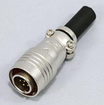
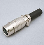
Q: What is the configuration of the load cell cable connector?
The standard configuration is bare lead wires. An NDIS-7P connector is also available as an option.
PRC03 Connector (Tajimi Musen)
Q: Do you offer cables that are resistant to kinking and bending?
TEAC's load cells utilize robot cables that are resistant to breaking and bending.
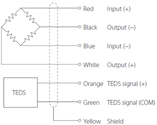
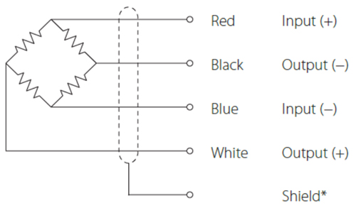
Q: Please explain the electrical connection between the load cell and the equipment.
Electrical connection of load cell with built-in TEDS
- Connect as shown in the illustration below. Incorrect connections could result in inability to balance and in errors occurring in the output voltage when loads are applied.
Using a cable with bare lead wires
Q: What's TEDS?
TEDS-compatible sensors store their model name, serial number, sensitivity, and calibration data in memory.
This allows for automatic sensor identification and indicator programming, helping to prevent configuration errors.
Q: Is sensitivity calibration necessary when connecting a load cell to an indicator?
Yes, it is necessary.
The indicator/amplifier and load cell must be calibrated after connection.
https://loadcell.teac.com/support/teds.html
Q: What is the response frequency of the load cell?
The response frequency is approximately one-tenth of the natural frequency of TEAC load cell products.
Q: We are using a tension-type load cell.Is it not possible to measure in the + (compression) direction?
Although it can be used for compression applications, it has not been tested for this purpose at the time of shipment, so the measured values are not guaranteed.
Please use a load cell that has been tested for both tension and compression.
Q: Are there any conditions to be mindful of when choosing a location for a load cell?
The load value is unstable. Additionally, this can lead to uneven loading, which may cause malfunctions.
Please install the unit on a flat structural surface that can fully support the intended load.
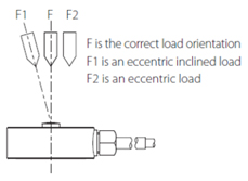
Q: Precautions when placing loads on the unit
- Make sure the load is perpendicular to the surface to which this unit is attached.
- Apply the load so that it is centered on the center of the unit. If the load is not centered (eccentric load), twisting, for example, and measurement errors could occur. This could even result in damage.
Q: Please tell me the deflection at the rated capacity.
| model | Rated Capacity (R.C.) | Deflection (mm) |
|---|---|---|
| TU-BR-G | 200N | 0.23 |
| 500N | 0.19 | |
| 1kN | 0.18 | |
| 2kN | 0.21 | |
| 5kN | 0.14 | |
| 10kN | 0.2 | |
| 20kN | 0.23 | |
| TU-CR(T)-G | 50N | 0.42 |
| 100N | 0.35 | |
| 200N | 0.3 | |
| 500N | 0.25 | |
| 1kN | 0.21 | |
| 2kN | 0.24 | |
| TU-FSRSP(T)-G3 | 50N | 0.03 |
| TU-FSRSP2(T)-G3 | 10N | - |
| 20N | - | |
| 100N | - | |
| TU-MBR(T)-G3 | 2N | 0.017 |
| 5N | 0.014 | |
| 10N | 0.013 | |
| 20N | 0.016 | |
| 50N | 0.04 | |
| 100N | 0.056 | |
| 200N | 0.047 | |
| TU-MXR2(T)-G | 10N | 0.02 |
| 20N | 0.02 | |
| 50N | 0.02 | |
| 100N | 0.01 | |
| 200N | 0.01 | |
| 500N | 0.01 | |
| TU-GR-G | 5kN | 0.03 |
| 10kN | 0.03 | |
| 20kN | 0.03 | |
| 50kN | 0.04 | |
| 100kN | 0.04 | |
| 200kN | 0.06 | |
| 500kN | 0.04 | |
| 1000kN | 0.09 |
| model | Rated Capacity (R.C.) | Deflection (mm) |
|---|---|---|
| TU-NR-C-G | 1kN | 0.01 |
| 2kN | 0.02 | |
| 5kN | 0.02 | |
| 10kN | 0.02 | |
| 20kN | 0.02 | |
| 50kN | 0.02 | |
| 100kN | 0.02 | |
| 200kN | 0.03 | |
| TU-QR(T)-G3 | 50N | 0.009 |
| 100N | 0.007 | |
| 200N | 0.009 | |
| 500N | 0.014 | |
| 1kN | 0.017 | |
| 2kN | 0.023 | |
| TU-PGRS-G | 100N | 0.090 |
| 200N | 0.086 | |
| 500N | 0.060 | |
| 1kN | 0.060 | |
| 2kN | 0.060 | |
| 5kN | 0.060 | |
| 10kN | 0.060 | |
| 20kN | 0.060 | |
| TU-PGRH-G | 200N | 0.088 |
| 500N | 0.083 | |
| 1kN | 0.085 | |
| 2kN | 0.060 | |
| 3kN | - | |
| 5kN | 0.065 | |
| TU-UJ(T)-G | 1N | 0.42 |
| 2N | 0.35 | |
| 5N | 0.24 | |
| 10N | 0.2 |
| model | Rated Capacity (R.C.) | Deflection (mm) |
|---|---|---|
| TC-AR(T)-G6/8 | 20kN | 0.03 |
| 50kN | 0.07 | |
| 100kN | 0.06 | |
| 200kN | 0.09 | |
| TC-BSR-G3 | 10kN | 0.020 |
| 20kN | 0.040 | |
| 50kN | 0.050 | |
| TC-FR(T)-G6 | 500N | 0.15 |
| 1kN | 0.1 | |
| 2kN | 0.07 | |
| 5kN | 0.07 | |
| 10kN | 0.05 | |
| TC-FSRSP(T)-G3 | 50N | 0.03 |
| TC-FSRSP2(T)-G3 | 10N | - |
| 20N | - | |
| 100N | - | |
| TC-KR(T)-G6 | 5kN | 0.03 |
| 10kN | 0.03 | |
| 30kN | 0.03 | |
| 50kN | 0.02 | |
| 100kN | 0.02 | |
| 200kN | 0.02 | |
| TC-LPR(T)-G6 | 500N | - |
| 1kN | 0.080 | |
| 3kN | 0.045 | |
| TC-MFSR(T)-G | 20N | - |
| 50N | - | |
| TC-MR(T)-G3 | 5kN | 0.008 |
| 10kN | 0.016 | |
| 20kN | - | |
| TC-NSRSP(T)-G3 | 50N | 0.007 |
| 100N | 0.012 | |
| 200N | 0.013 | |
| 500N | 0.015 | |
| TC-NSR(T)-G3 | 1kN | 0.03 |
| 2kN | 0.03 |
| model | Rated Capacity (R.C.) | Deflection (mm) |
|---|---|---|
| TC-SR(T)-G | 5N | 0.02 |
| 10N | 0.01 | |
| 20N | 0.02 | |
| 50N | 0.01 | |
| TC-SR-G3 | 5kN | 0.005 |
| 10kN | 0.003 | |
| TC-SR(T)-G3 | 100N | 0.01 |
| 200N | 0.02 | |
| 500N | 0.01 | |
| 1kN | 0.007 | |
| 2kN | 0.005 | |
| TC-USR(T)17-G3 | 1N | - |
| 2N | 0.025 | |
| 5N | 0.03 | |
| TC-USR(T)23-G3 | 1N | - |
| 2N | 0.02 | |
| 5N | 0.03 | |
| TC-USR(T)29-G3 | 10N | 0.025 |
| 20N | 0.03 | |
| 50N | 0.04 | |
| 100N | 0.03 | |
| TC-USR(T)30-G3 | 0.5N | 0.07 |
| 1N | 0.06 | |
| TC-USR(T)34-G3 | 200N | 0.05 |
| 500N | 0.065 | |
| 1kN | 0.04 | |
| 2kN | 0.03 | |
| TC-XR(T)-G6 | 20kN | 0.02 |
| 50kN | 0.02 | |
| 100kN | 0.03 | |
| 200kN | 0.03 | |
| 300kN | 0.03 |
| model | Rated Capacity (R.C.) | Deflection (mm) |
|---|---|---|
| TT-FR(T)-G6 | 500N | 0.15 |
| 1kN | 0.1 | |
| 2kN | 0.07 | |
| 5kN | 0.07 | |
| 10kN | 0.05 |
Q: Please explain resolution and accuracy.
Consider a sensor with a rated output of 100 mV and an accuracy of 0.1% being converted via an 8-bit A/D converter.
Resolution refers to the smallest value that a measuring instrument or display can detect. For example, if a sensor with a full-scale output of 100 mV is measured using an 8-bit A/D converter, since 8 bits = 2^8 = 256 levels, the minimum resolution becomes 0.390625 mV.
Regarding accuracy, the error is expressed as a percentage of the rated capacity, indicating the deviation from the ideal straight line between the no-load output and the output under a rated capacity load. For example, since the accuracy of the sensor mentioned earlier is 0.1%, this means there is a possibility of an error of up to 100 mV × 0.1% = 0.1 mV in the measurement result.
In this case, the output signal containing a 0.1% error is converted to digital form with a resolution of 0.39 mV. For the measurement system as a whole to accurately measure the actual phenomenon in a broad sense, both accuracy and resolution must be set to high levels.
As described above, while resolution and accuracy may seem similar, they represent entirely different performance characteristics.
Q: What is the allowable input voltage?
It refers to the maximum voltage that can be applied to the input terminals while the load cell remains within its specifications and can be used continuously.
Q: What is the response frequency of the load cell?
The response frequency is approximately one-tenth of the natural frequency of TEAC products.
Q: Please tell me which locations are unsuitable for installation.
Do not place the unit in the following types of locations.
Doing so could cause malfunction.
- Locations where it might be exposed to smoke or steam,such as near a kitchen table or humidifier
- Unstable locations, including unsteady stands and tilted places
- Locations that are very humid or dusty
- Locations that are exposed to direct sunlight
When not using the unit for a long time
For safety, cut the power supply when not using this unit for a long time.
Do not operate a damaged unit.
Q: Conversion Table to SI Units
| N | gf / kgf / tf |
|---|---|
| 0.5N | 51gf |
| 1N | 102gf |
| 2N | 204gf |
| 5N | 510gf |
| 10N | 1.02kgf |
| 20N | 2.04kgf |
| 50N | 5.1kgf |
| 100N | 10.2kgf |
| 200N | 20.4kgf |
| 500N | 51kgf |
| 1kN | 102kgf |
| 2kN | 204kgf |
| 5kN | 510kgf |
| 10kN | 1.02tf |
| 20kN | 2.04tf |
| 30kN | 3.06tf |
| 50kN | 5.1tf |
| 100kN | 10.2tf |
| 200kN | 20.4tf |
| 500kN | 51tf |
| 1000kN | 102tf |
